


Description
The QHY5III200M Planetary Guide Camerais a new generation QHY5III V2 series camera, using a domestic CMOS, with excellent quality, and near-infrared high sensitivity similar to the QHY5III462C. QHY5III200M is also the first mono CMOS planetary camera with near-infrared enhancement characteristics QHY developed. In addition, the 4um large picture elements to make it easier to use for guiding.
The product comes with filters including the IR850 filter.
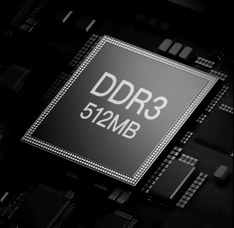
The QHY5III (Ver. 2) series planetary and guiding cameras are all equipped with a 512MB DDR3 image buffer which can effectively reduce the pressure on computer transmission, a great help for planetary photography which often requires writing a large amount of data in a short period of time. Some deep-sky astrophotography cameras on the market today only have 256MB, for example.
In comparison, the 512MB DDR3 memory of the new 5III (Ver. 2) series cameras represents a significant upgrade.
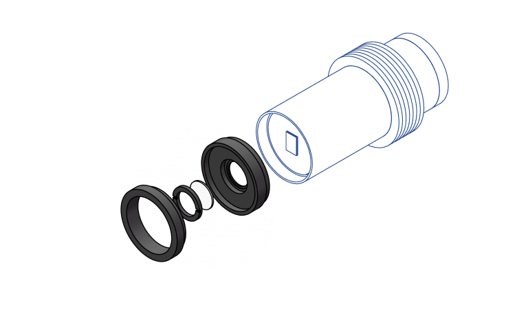
QHY5III (Ver. 2) series cameras have adopted a new front-end design with better compatibility. The new front end supports 1.25″ interface of telescopes and is also compatible with CS-port lenses and C-port lenses, and can shoot with C/CS-port lenses with filters attached.
A 1.25″ framed filter can be fitted with the front end, and a frameless filter can be fitted on the front part of the upper CMOS. The size of the filter glass that is compatible here varies depending on the size of the sensor, but is basically a standard lab filter specification. Compared to the more expensive astronomical filters, lab filters tend to be less expensive and have a wider variety of bands, allowing you to develop more uses and applications for them.
The new QHY5III (Ver.2) series cameras all use the USB3.2 Gen1 Type-C interface. Compared to the USB3.0 Type-B interface used in the previous generation, the Type-C interface has a longer life and is more flexible.
Tips: It is recommended to use the official standard Type-C data cable of QHYCCD. As the market is flooded with a large number of poor-quality Type-C cables, casual use may lead to the camera malfunctioning. If you use your own spare cable, please make sure it is a high-quality cable.
The custom interfaces of the previous generation of planetary cameras and guiders has been replaced in the QHY5III (Ver.2) cameras with a more universal ST-4 compatible guiding interface. Now, even if the guiding cable is lost or damaged, you will be able to easily get a replacement on the market at a low cost.
 The new QHY5III (Ver.2) series of cameras is equipped with a status indicator at the back of the camera. If the camera experiences an abnormal status, the multi-colored indicator light will help to determine the situation with different colors signifying different conditions. During normal operation this indicator light is off, so there is no worry about light contaminating the image.
| Model | QHY5III200M |
| CMOS Sensor | SC2210 |
| Pixel Size | 4um*4um |
| Effective Pixel Area | 1920*1080 |
| Effective Pixels | 2 Mega Pixel |
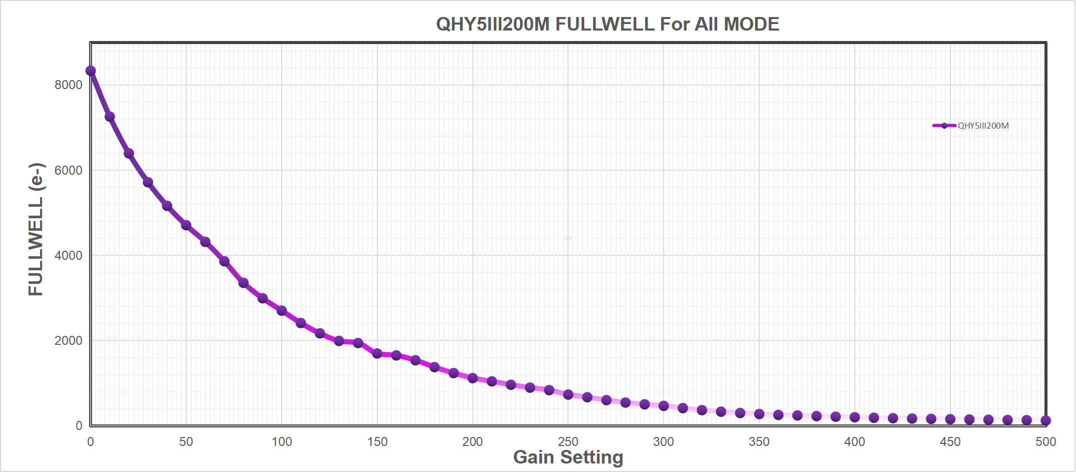
| Fullwell | 8000e |
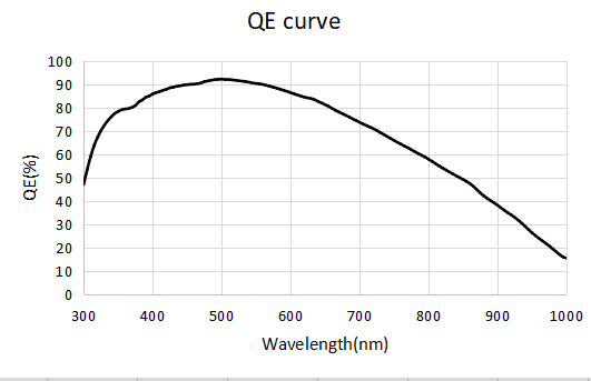
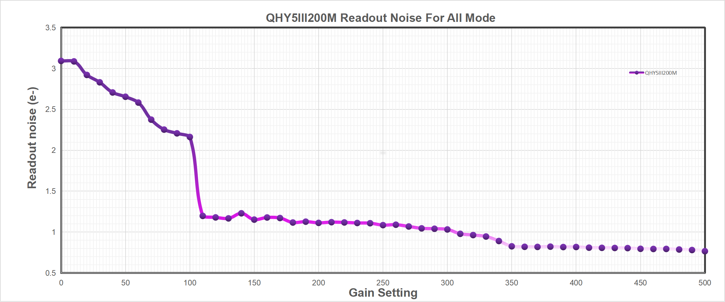
| Readout Noise | 0.75e – 3e |
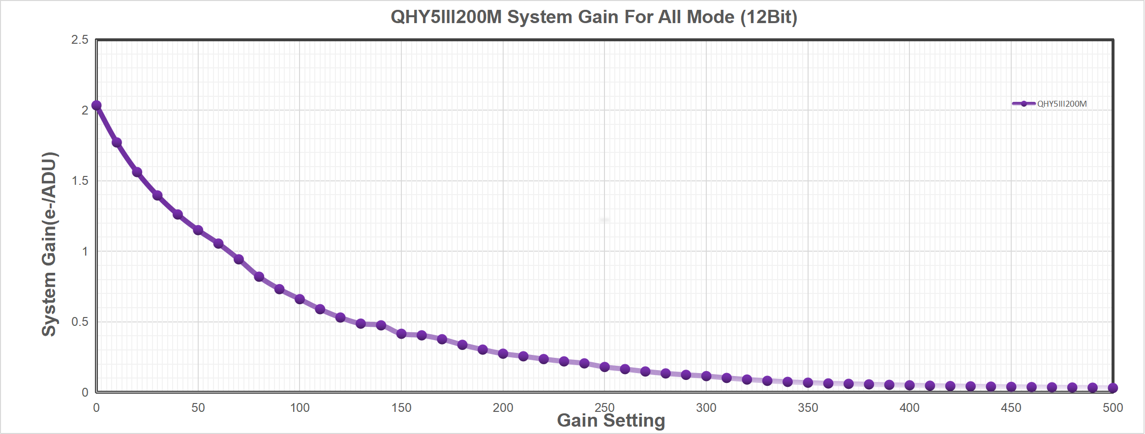
| AD Sample Depth | 12bit (output as 16bit and 8bit) |
| Built-in Image Buffer | 512MB DDR3 Memory |
| ROI Frame Rate | Full Resolution 96.5FPS @8BIT 60FPS @16BIT
960Lines 187FPS @8BIT 116FPS @16BIT 480Lines 209FPS @8BIT 130FPS @16BIT |
| Exposure Time Range | 15us-900sec |
| Shutter Type | Electric Rolling Shutter |
| Computer Interface | USB3.2 Gen1 Type-C |
| Guide Port | st4 |
| Telescope Interface | 1.25-inch, compatible with CS-port and C-port lenses by replacing the front-end connector (An IR AR glass and an IR850nm filter are included in the standard version.) |
| Back Focal Length | 17mm |
| Weight | 90g |
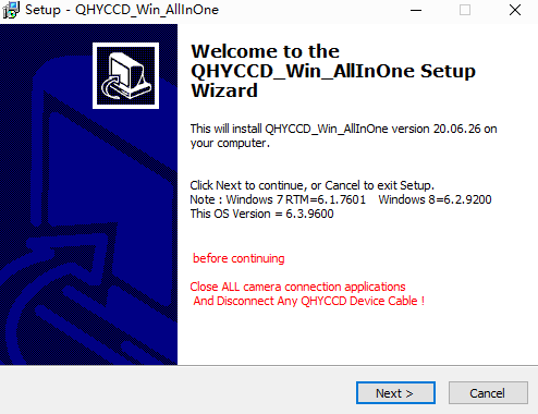
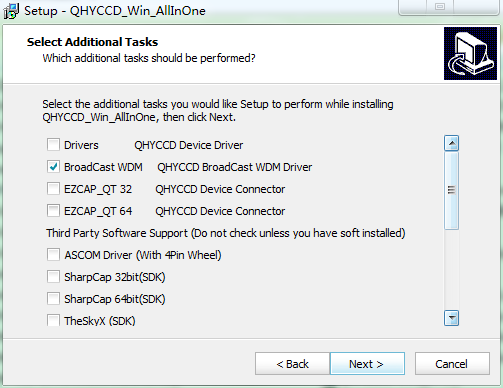
All-in-one Pack (Windows) is for all QHYCCD USB3.0 devices, including all Cooled CMOS cameras, QHY5III and QHY 5II series, QHYCFW3. We recommend you choose “Stable Version” as usual.
In this pack there are:
1. System driver. It must be installed to make devices work.
2. EZCAP_QT: it’s developed by QHYCCD which could be used in QHY devices tests, simple capture tasks, and above all, the management of updates. So even if you won’t use EZCAP_QT as your main capture software, we suggest you install it to get the latest information of QHY drivers/SDK updates.
3. Ascom driver: Ascom Platform is supported by most astronomy devices which connect to Windows.
4. SDK: SDK is the file of “.dll” format. With this the device can be identified in other capture software.
5. SkyX Plugin: special support for SkyX.
6. QHYCCD BroadCast WDM Driver: It is a broadcast driver that supports QHYCCD cameras with video broadcast function, which can meet the needs of customers to send video images to other target software.
How to install it?
Take SharpCap (x64) for example:
Before the installation, make sure you’ve already installed SharpCap (X64) on your PC;
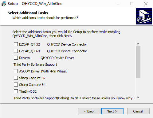
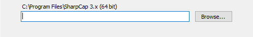
Then click ”Third Party Software Support” – “SharpCap 64”, the pack will detect the location of SharpCap files and install automatically; if not, please manually select root directory of SharpCap where you installed it, like: C:\Program Files\SharpCap 3.2 (64 bit)
Here we mainly take QHY5III462C as example. This User Guide can be applied to all QHY5III series Camera.

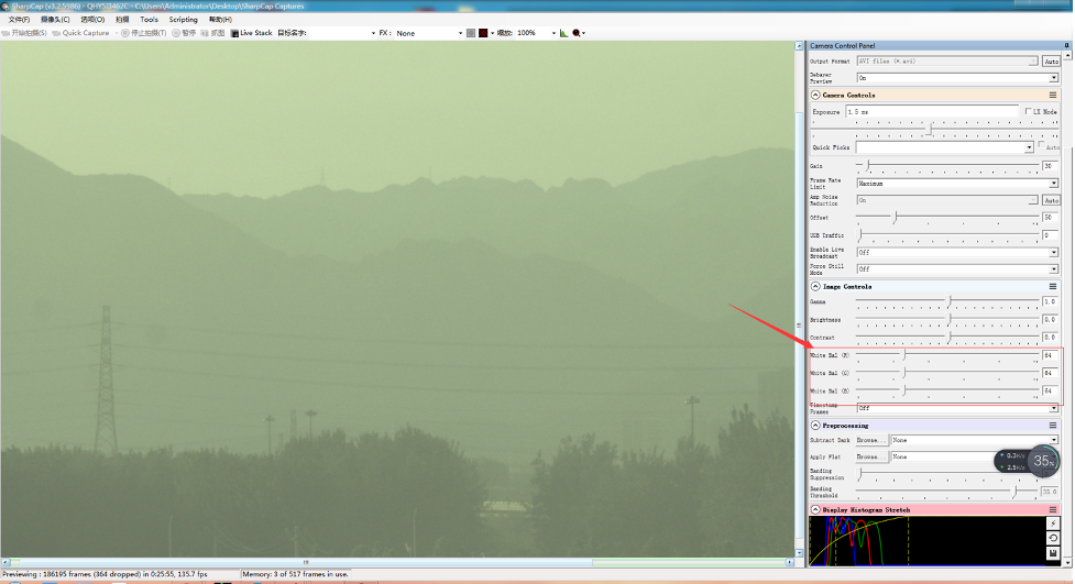
Adjust OFFSET. You will find that when the lens cover is closed and the image is completely black, the background of the image is still not completely black. Therefore, you need to adjust the OFFSET value to make the image darker. Generally speaking, for planetary shooting, setting the image background to very dark is not a big problem. For deep space shooting, a certain background should be retained, and it should not be completely black, otherwise it will lead to the loss of a weak background cloud.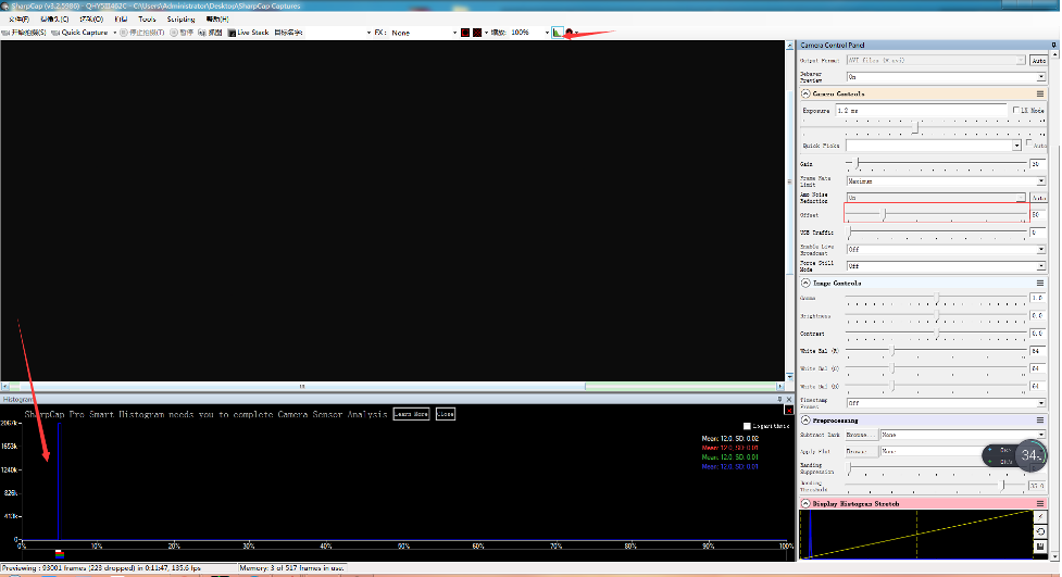
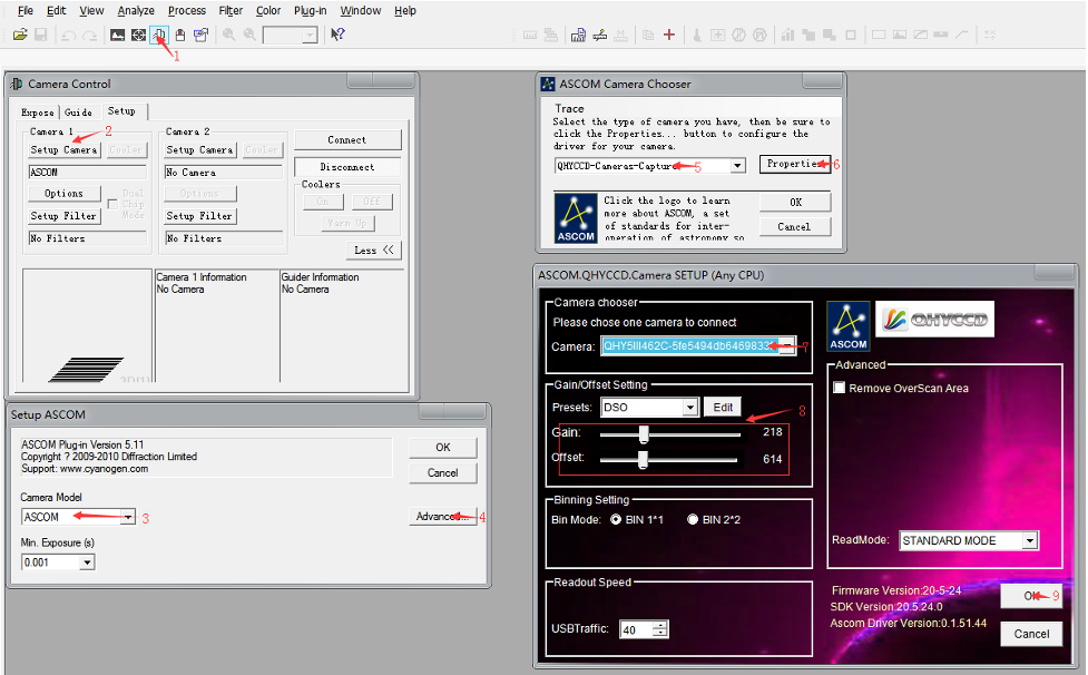
There are many astronomical software support ASCOM, you can connect QHY5III462C through ASCOM. Note that currently QHY5III462C only supports the ordinary ASCOM shooting mode, and does not yet support the ASCOM video mode. In order to obtain the maximum dynamic range and effect, the ASCOM driver uses the maximum number of digits transmission by default (for QHY5III462C, 12-bit), the image is stored in a 16-bit format, and the lower bits are filled with zeros.
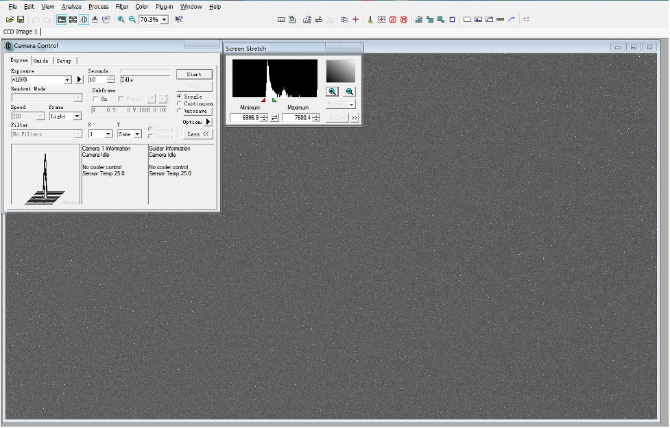
Use MAXIMDL for Plantery Imaging
When changing the exposure time to a long exposure time, the CMOS chip may output a few frames of short exposure. These frames may be output, but the subsequent frames will be normal long exposure frames.
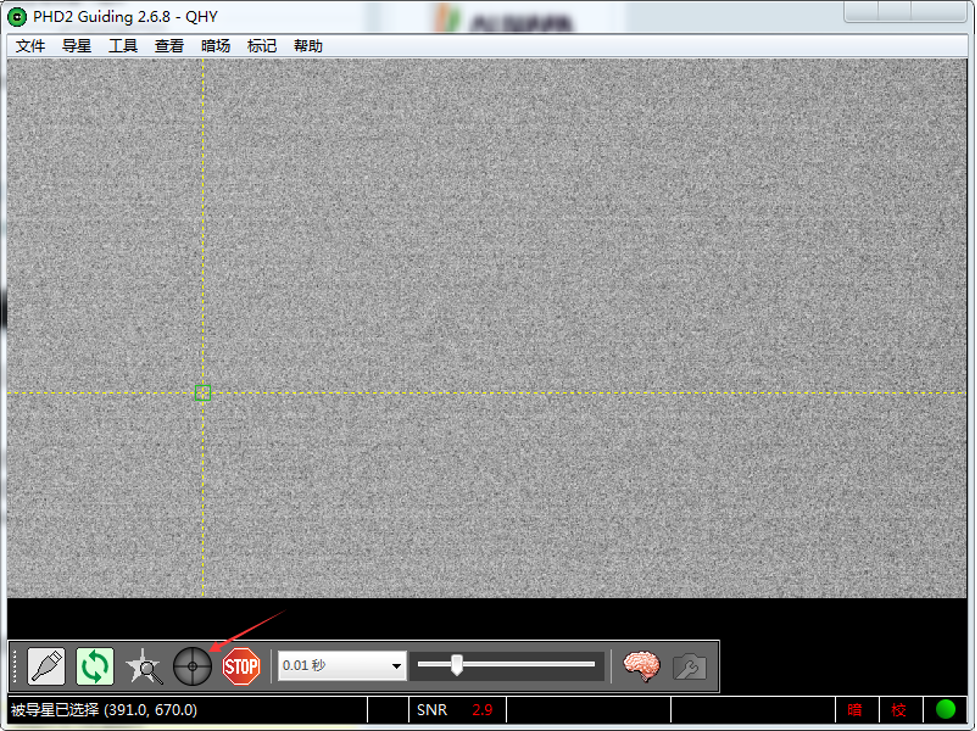
Using PHD for Guiding
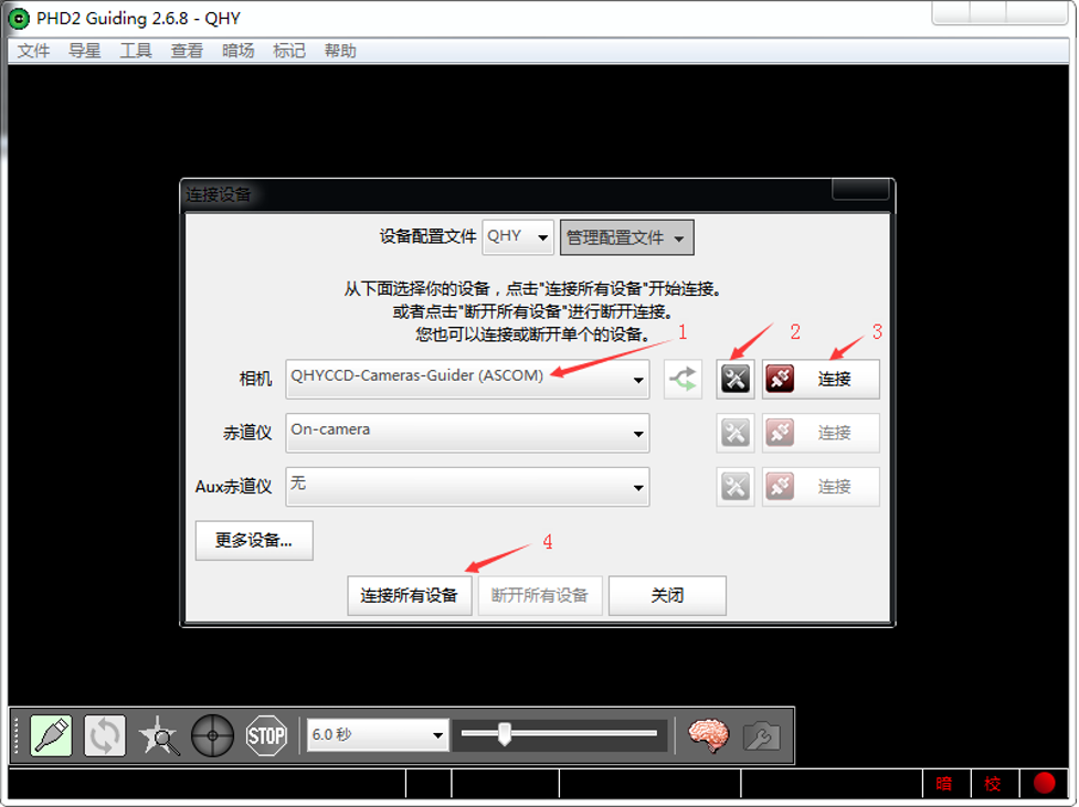
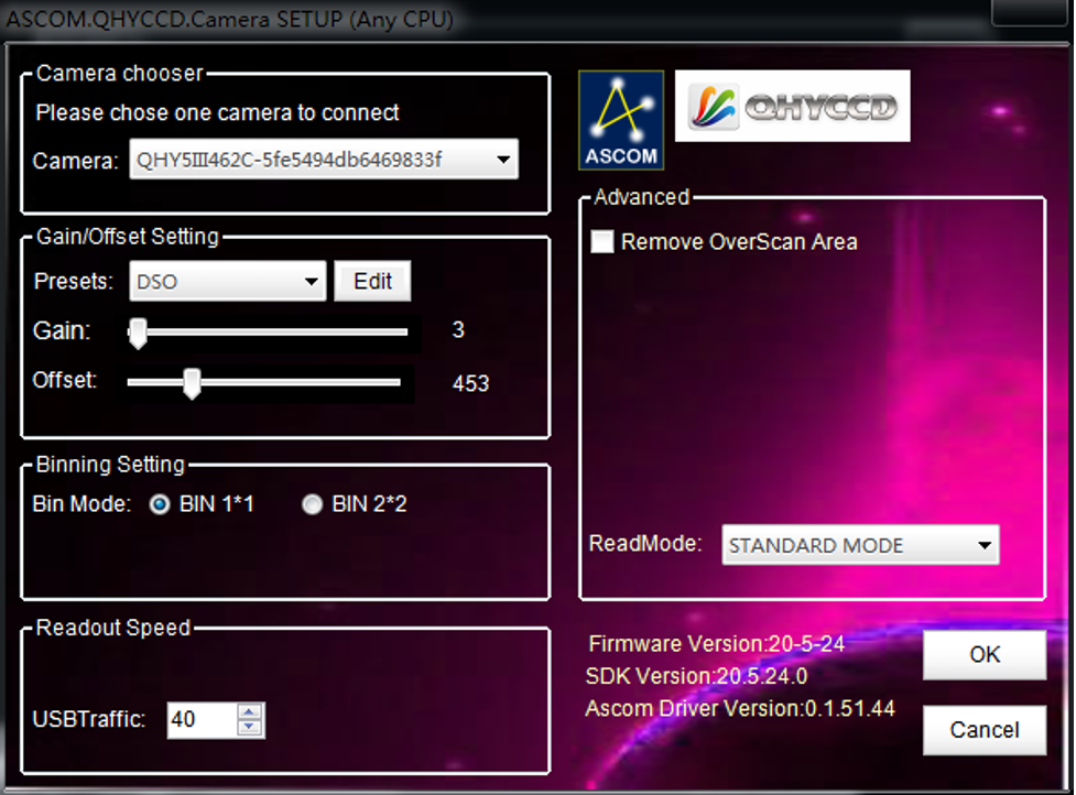
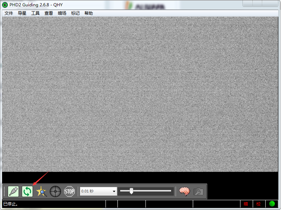
Select a star point on the screen, a green frame appears, and then select to start calibrating the equatorial mount and guide star.
QHYCCD BroadCast WDM Camera is a broadcast driver that supports QHYCCD cameras with video broadcast function, which can meet the needs of customers to send video images to other target software. For example, use sharpcap to connect a WDM-enabled camera, and the sharpcap display video image can be sent to other WDM-supported software for display, which is suitable for video online broadcast applications.
The installation process is over, right-click the computer to find the device manager, and check that the image device name is QHYCCD BroadCast WDM Camera, which means the installation is successful.
QHY5III Guiding Line Sequence Definition

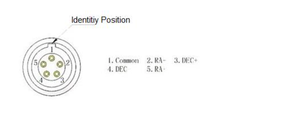
The guide circuit contains an optocoupler isolator. The COMMON pin is generally connected to GND. Usually the four direction pins from the equatorial mount are internally pulled up on the equatorial mount circuit, so when the QHY5III sends out the guide star pulse, the optocoupler pulls it down to realize the output of the guide star command.

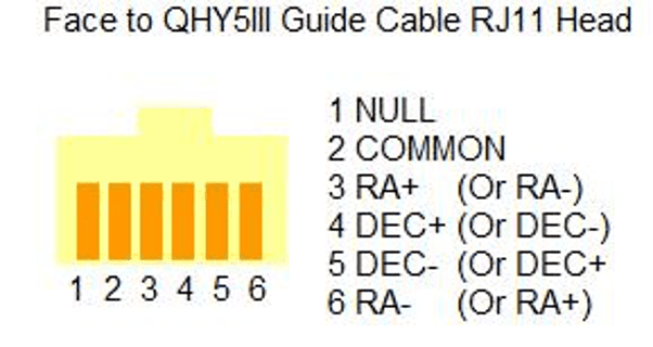
The line sequence of the socket at the equatorial mount is

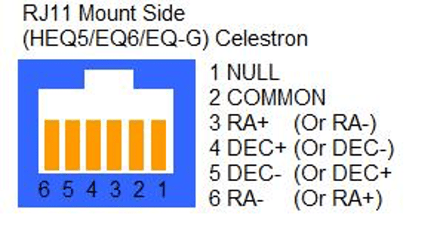
If you use other types of equatorial mounts, please confirm whether the wire sequence is the same as the above.
Because QHY5III series cameras have a very high frame rate and data volume, not all computers can reach the maximum frame rate. Generally I7 quad-core is no problem. However, the CPU occupancy rate will also affect the maximum frame rate, so when using QHY5III, try to close other programs that occupy the CPU and free up the CPU to process the data. If the CPU usage is too high, the program will respond slowly or even crash.
| Cooled CMOS Camera | Bayer |
| QHY600C | RGGB |
| QHY268C | RGGB |
| QHY410C | RGGB |
| QHY367Pro | RGGB |
| QHY128Pro | RGGB |
| QHY294C | RGGB |
| QHY247C | RGGB |
| QHY168C | RGGB |
| QHY165C | RGGB |
| QHY163C | GRBG |
| QHY183C | RGGB |
| QHY174C | RGGB |
| QHY178C | GBRG |
| QHY290C | GBRG |
| QHY224C | GBRG |
| Planetary and Guiding | Bayer |
| QHY5III174C | RGGB |
| QHY5III178C | GBRG |
| QHY5III224C | GBRG |
| QHY5III290C | GBRG |
| QHY5III462C | GBRG |
| QHY5III485C | RGGB |
| QHY5L-II-C | BGGR |
| QHY5P-II-C | GBRG |
| Cooled CCD Camera | Bayer |
| QHY8L-C | GBRG |
| QHY10-C | RGGB |
| QHY12-C | BGGR |
Now the ratio R”:G”=(R+bias)/(2R+bias) and it is not equ to 1:2. It shows the bias will effect the true value of the R:G. And the ratio of R:G will arious when the image light changed. It is hardly to correct with a fixed ratio.
But for DSO capture, You should keep the offset above zero and avoid the background is cut off. A background from 1000-5000 is a good value(16bit mode) for DSO imaging.


Reviews
There are no reviews yet!